Friday, December 22, 2006

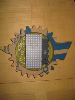
I put the LEDs in and put it in a 1/3 drop resin medal. Red for this prototype. I'll make white and blue medals as well. I ended up going with 180 ohms in the reds after all. That brings them to just at 20mA whereas on the white LEDs its more like 14 or 15mA. The whites actually seem a touch brighter than the red even so.

Overall the effect is wonderful. In the picture the area around the LED is saturated but it looks great in person. Woot!

Success for the Serial Medal

The very first PCB for the serial medal worked flawlessly on the first attempt! I know it looks a little screwed up in the picture, but that is because of my crappy cell phone camera's very slow shutter speed. Anyway, I am terribly excited! This thing is finally coming together. I need to run out to get resistors for the red LEDs I want to put in it. 180 Ohms works great for the white LEDs but the reds have a much lower voltage drop. And I probably need to snag some 47s for the row selectors as I just had 58s on hand. Although, it looks fine with 58s.

To be certain I need to make up the other four boards and sit on them for a few days to be sure they are stable. Assuming that goes OK the next step will be to finish the work up on the Bill of Materials. I'm pretty sure I'm going to need some sponsorship to get the cost under $15 per a medal. However, I have high hopes for getting the PCBs themselves sponsored which may land me right in the $13 range.

Sunday, December 17, 2006

Brazing


I gave aluminum brazing a shot this weekend. Its pretty cool really. I got a pound of rods from DuraFix. (Check their sales video. Another company that sells the stuff and also has a video is Aluminum Repair.) I also picked up a mapp gas torch kit from a hardware store. The idea is that you get the aluminum up to a certain temperature such that the silver alloy in the rods will melt, but the aluminum itself won't. The alloy act as a sort of metal glue.

It turns out that the metal needs to be pretty clean and further it has to be cleaned the right way. A stainless steel brush was provided with the rods but I soon discovered you really need two: one for pre-cleaning and one for manipulating the alloy while hot. To to make a joint its a good idea to tin both sides.

It also turns out that mapp gas is plenty hot enough to melt aluminum. I slagged a couple of pieces before I got the hang of it. Probably need to back down to propane or even butane.

After around five or six attempts I got a pretty strong joint. Its the one in the picture. I managed to crack the joint open but it's still pretty strong and it took a hell of a beating just to get to that point. To be able to make that strong of a joint with a couple hours practice is pretty cool. Supposedly, after I master the techniuqe the joints will be stronger than the original metal.

I figure this brazing thing can be very useful for making custom aluminum chassis for my robots. When it comes time to make my RoboMagellan bot water tight I think I'll be using this technique.

Anyway I just wanted to do a quick post with a couple links. Sorry its not longer and doesn't share the experience more in depth.

Saturday, December 09, 2006

The Serial Digital Medal PCB Layout

I've also finished the PCB layout for the circuit. I want to fuss over it a bit more, because 5 prototypes boards run me about $95 . Thus any mistake is an expensive one. I'm still kicking myself for the too-small hole sizes from the very first version of the board.

However, the last layout took about a week and a half of work to get it 100% routed to where I was happy. This board auto-routed fully on the second placement attempt. I still needed to do some manual re-routing but nothing too serious. Plus, all the normal lines are 10 mil and the power lines are 15 mil. Each chip has its own 0.1uF anti-noise cap to boot. I'm hopeful the intermittent noise and dust problems of the past will be gone from this design. I'll still probably get it a good solid flux cleaner bath though.

Chances are I'll put PCB layout in today or Monday. I kinda wish I could have them for tomorrows meeting, but that meeting is going to be busy anyway and I absolutely don't wont to rush this. Rushing was a big factor in all the mistakes of the previous version of the medal.

This is starting to get exciting again!

Serial Digital Medal now on ATtiny45


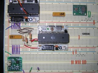
So the medal is now working off of the ATtiny45 instead of the ATmega32. You can see the 8 pin DIP just to the left of the red dip switch. The display is working great with no glitches. I'm not sure what caused it before but if the problem doesn't come back I should be good. It might have been a loose connection or something. There are a lot of wires for this circuit.

In the picture the text looks pretty bad, but its really my cell phone camera. In real life the display is perfect. I still can't find my good 3MP cannon. :(

If you look to the lower left in the picture you'll see two more ATtiny45's. Those are the two MCUs I bricked before realizing that the programmer was still set to ATmega32. I wondered why the display started out slow and then actually got SLOWER when I set the fuses for a faster clock. Doh! I hope someone in the club with an STK500 can get them back for me.

Wednesday, December 06, 2006

Serial Digitial Medal working!

So the problem with the breadboarded serial medal was that the data and the strobe line was backwards and I had shifted the pins connections by one on one of the displays. Nothing that required an o-scope/logic analyzer at all. If I had bother to trace the lines I would have found it. Once I fix the problem the code started working pretty well. Oh well, the device I bought looks fairly neat. At the very least the software is super simple to use.

The breadboard is still using the ATmega32 at the moment but there is not much logical difference in this case. Still, to be safe I will through the ATtiny45 in there before I put the board order in.

Also the display isn't perfect. It does seem to glitch some times on the capital letters. It doesn't look too terrible, but I'd like to figure it out. It seems to be associated with the character rather than a particular location on the display. So it could be the algorithm. Overall it still looks good even with the glitch.

Tuesday, November 28, 2006

The Serial Digital Medal Design


So I mentioned before that, to reduce cost and pin count, we were changing the digital medal design over to some serial driver chips. I'd like to talk about the new design a little.

The big cost saver is the ability to use the ATtiny45 (2.13USD Qty: 1) instead of the ATmega32 (8.28USD Qty: 1). Previously, the driver chips that we were using were really just gangs of transistors. Each transistor had an input and output pin. Hence the MCU pin count requirement to operate the chips was high and forced us to the ATmega32.

After some searching our members came up with transistor arrays that, instead of individual transistor inputs feature a clocked serial data input line that feeds into a shift register and a strobe line that latches the shift register bits up to the (now internal) transistor inputs. Additionally the chips feature a serial data out line that leads away from the far side of the shift registers. The source driver, U1 in the schematic and used to select rows in the 5x7 LED matrix displays is the MIC5891. The sink drivers, U2 and U3 in the schematic, used to select columns, are two A6821's.

So in the new design the three driver chips and the MCU are daisy chained: Serial Data Out connects to Serial Data in, one chip after another with common clock and strobe lines. From the point of view of the MCU this forms a single shift register that is 24 bits wide. The first two bytes shifted out become the column selectors and the final byte becomes the row selectors. The idea is for the MCU to clock out three bytes, hit the strobe and then repeat. This basic scheme uses a mere three pins to reset the state of all row and all column selectors and is why the ATtiny45 will work.

Of course, this is just the design. I have the circuit fully breadboarded up and can see the clock, data and strobe lines popping away at the first chip in the daisy chain, but nothing is coming out of the other side of the shift register on its Serial Data Out line. Most likely this mean that something is wrong with the clocked data that the MCU is emitting and thus the first chip isn't properly receiving the data in the first place. I only own voltmeters so it is hard to tell what is wrong with the signal. I've ordered a cheap O-scope/Logic Analyzer from Hobby Lab that should help me out. It should present me with timing diagrams of the signals on clock, data and strobe lines that I can then compare to the example timings in the data sheets for the chips. Hopefully there will be something I can do to correct the signal. My concern is that since I'm using the Bascom Shiftout command, that the only solution will be to shift to C for greater control of the timing. Maybe it won't suck too bad if I really do have to port the code though.

Monday, November 13, 2006

Chibotica Fall 2006

Chibotica went pretty well. The turn-out was lower than I had hoped for. To my knowledge we only got one person from iHobby Expo. Still, I'm convinced the the Outreach program is the right thing to do. If I can convince the member to have our next fall contest at iHobby Expo, I think we will be quite well attended.

But again the show itself was very fun. The Mini-Sumo especially was dramatic. Its great that Mel's grand-daughter won it. I wish I could have given her a medal as reward. But oh well.

Monday, November 06, 2006

Digitial Medal Super Funness!

Well, I'm still working on the damn digital Medal. I have one fully working. It looks great actually. (I'd post a pic but I can't find my camera) But of course, we are going to change the design. The board is just not stable. I had one that worked great after construction but then it failed a couple of days later. It improved a lot with a alcohol bath. So at least part of my problem is just dust and debris. I need to buy flux cleaner so I can clean these boards too.

However, my ability to experiment further is limited because I have no good boards left. Basically i can try to repair one malfunctioning board. I will do that, but it won't bring me the confidence that I truly know what is going on with the boards. I am NOT going to order more boards. At $95/five they are just too expensive.

Anyway, another problem with the board is that it is expensive. The massive number of pins required on the MCU means that a ATmega32 is required. However, the MCU can't drive the LED matrix directly so driver chips are required. Some of the members rounded up some driver chips that take a serial input and can be cascaded. This means that the MCU now only needs three pins instead of 22. So we can go from an ATmega32 to an ATtiny45. Its a pretty big savings.

Thursday, October 26, 2006

Still More Digital Medal

Weirdness.

Having missed all my deadlines for the medal I can now relax and go back to the drawing board to get the stupid thing right. I have breadboarded the entire circuit to see where I went wrong.

I got the same sort of weird errors on the breadboard. That's good from a troubleshooting perspective. When I traced it back I came all the way to the MCU pins. Some of the MCU pins can't hold an Active High under any condition except open. The inputs to the ULN2803A are decently high impedance I think. But some of the MCU pins can do it. Others can.

I may have been mis-handling the MCUs the whole time and destroying outputs at random. That could explain what I've been seeing in all my prototypes. I'm going to swap MCUs tonight and see if the symptoms change.

iHobby Expo

iHobby Expo was pretty cool. Its the largest outreach I've done so far. I learned a lot. The Hobby RC crowd was actually pretty interested in what we were doing. That was a little bit of a surprise. I think we'll get at least a couple new members out of this. Woot!

Wednesday, October 04, 2006

Disappointment

Pretty bummed tonight. I got the new corrected PCB boards today as well as the components to populate them. The boards went together easy. No more hole size silliness. I knew already to solder the UDN2981 on the bottom of the board.

However, the board doesn't work. A few columns light up. The best thing I can say is that soft power works. I have no idea of what's wrong at this point and the chances of correcting it by meeting time are slim.

Thursday, September 21, 2006

Digital Medal sort of working Part 2

So, some heat applied to the row seven current limiting resistor fixed the dead row number seven. As for the doubled up column, I've determined that the column is shorted to Vcc on the MCU to transistor array link. That has to be an assembly issue. An unpopulated board doesn't have the problem.

So now the only worry is the soft power. Can it handle the load? Why is it dropping out to two volts in the present circuit? The short doesn't draw that much current, but since I don't know exactly where it is, I can't be sure of its full effect on the circuit.

I'd like to just cut the column signal line to see if I can get rid of the soft power problem, but its really hard physically. Plus there is no guarantee the as to the extent of the short. Maybe I should just test the load carrying capability with a false load? But what if the load is not the real issue? Hmmm. Hmmm. I will have to ponder it for a while.

Tuesday, September 19, 2006

Arrrr


My pirate name is:


Black Roger Rackham


Like anyone confronted with the harshness of robbery on the high seas, you can be pessimistic at times. You have the good fortune of having a good name, since Rackham (pronounced RACKem, not rack-ham) is one of the coolest sounding surnames for a pirate. Arr!


Monday, September 18, 2006

Li-ion Batteries


So today, bored at work, I began to think of the Li-ion batteries I got from Eddy some time back and how I might connect them. A lot of folks just solder the pads, but I kinda wanted to do a removable pressure contact type thing similar to what cell phones do. (The battery is actually intended for a cell phone.) I remember my old cell phone had theses sort of spring loaded plunger style contactors the rear battery door pushed the battery pads onto.

Anyway I went looking for the contactors, thinking they were custom and I'd never find them. I found these .1" Mill-Max spring loaded headers but, having only my faulty memory, felt sure that the battery pads were well over a .1" pitch. To my delight, when I returned home and bothered to check I discovered that my cell phone plunger things looked exactly like the Mill-Max headers and that the battery pads were in fact .1" pitch.

This looks like it will be a cool way to connect my batteries if I can come up with a good way to put pressure on the battery.

Digital Medal sort of working

Well I made some progress tonight. I have to short out the soft power circuit, but I can get the digital medal to mostly run. One column appears to be doubled up and the bottom row is completely dead. But the text is scrolling! Woot! I'll review the PCB design for the affected row and column, but it could easily be a drilled out hole issue. Its possible that heating the affected pad for a bit will get me a connection.

Anyway I'm happy to have progress.

Digital Medal Struggle

Sigh. So, the digital medal has problems. Not the least of which is the time and energy I have available to work on it. The worst problem is the damn hole sizes. I trusted the print out as a sort of eye-ball measurement that all the hole sizes were OK. They weren't. I have to drill out a lot of holes. The worst of that is for the LED displays that can't be soldered on both side. I have to drill a second hold very close the pad and run wire-wrap wire through it and the main hole to get a good mechanical and electrical connection to both sides of the pad.

The next problem is the third transistor array that was thrown in at the last minute. I guess I miscommunicated with the fellow who did the schematic for me. I though I had understood him to say that he'd prototyped the circuit. He hadn't done it for this last minute add. First I discovered that power was backwards. I should have looked more carefully once I discovered that. But, no. I started on a second drilled out board only to discover that the inputs and outputs were also backwards.

So now I'm onto to the third drilled out board. Ironically this board is a touch easier because I don't have to cut traces to fix the power. Since the inputs and outputs on the UDN2981 were also reversed, if I solder the chip to the other side it will be connected perfectly on the current board. If this works I don't think I'm going to edit the board except for hole sizes.

Anyway, I should be able to get a bit of work on it tonight. Maybe I'll be able to light it up, who knows. *I WILL* get it working for the November games dammit.

Tuesday, September 05, 2006

Digital Medal

Well the Digital Medal Project has been consuming almost all my free time for what seems like a month now. It's almost done! Today I got the prototype boards and tried placing the components. It was designed to be tight. I was astounded when the components snapped into the center hole with the precision that I had measured them for. Its a perfect fit.

All was not perfect, however. The PCB program I used to make the board shows the .02 in holes a lot larger on print out than .02 really is. Either that or the board shop used the wrong size bit. $90 worth of prototype board an I have to drill out half the damn holes and solder on both sides. That going to be a bit of a trick for the LEDs but I think I know how to do it.

Oh, well, the finals should be damn near perfect.

Now to solder up a board and see if the circuit actually works! Boy that it would be amazing to have everything fall into place right at the last minute here. The Table top competition is this Sunday!

Monday, August 21, 2006

Direct InkJet PCB Resist Printing

So, over on the Home Brew PCB Yahoo group, this fellow, Volkan Sahin, announces one day that he has modified his inkjet to print straight on to copper PCB and gotten it to resist Ferric Chloride long enough to etch. And etch quite fine lines at that. I watched the thread that ensued with considerable interest. Then a little while later another fellow, Stefan Trethan, announces he's repeated Volkan's results. What's more he posts a very detailed description of the printer modification and printing procedure that James Newton captures with fidelity on his Wiki.

At this point I am salivating. I have to have a mod'ed printer like this.

So in this blog, among other things, I will chronicle my efforts to reproduce Volkan's and Stephan's fabulous results.

To begin, I got my C84 off eBay. Less than $30 shipped! The ink kit I got from MIS for $88 shipped. Heh. Still the ink should last a while. I only bought yellow, the stuff reported to resist the best and also a little black. I took a few CCs of the black and put it in the yellow as others had reported they'd done to improve the yellow's visibility on the PCB. Two or three CCs was all it took to turn the entire 4oz bottle of yellow to a dark nasty sort of grey. I loaded all four refillable carts for my Epson with this stuff.

I'm not going to chronicle the assembly and installation of the refillable carts for the Epson as this is a reasonably easy and time-tested procedure that is engineered to succeed. I got it right on the first try and lots more than two people have done it.

Anyway, before I began I wanted to test fire the intact printer on regular paper to make sure it sort of worked. I hadn't gone after the vacuum tube assembly that Stephan assured me I'd have to clean so I wasn't uber hopeful. On the first try, nothing came out. However, I took out the black cart, pulled and pushed the syringe while plugging into the bottom with the priming nozzle, and then reinserted and ran a nozzle clean from the maintance screen.

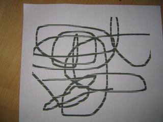
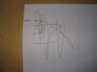
On the second run I got this:


That would be death for a PCB of course. So a day and another nozzle clean later the printer shaped up:
The black portion of the nozzle test (left slashing lines) is perfect even thought the color pattern is broken. (The color is loaded with the same stuff the black is, so who cares?) And the test squiggle drawn in Paint is un-broken except at the top and left where it was broken in the original Paint file.

Good results seeing as I haven't even touched the vacuum system!

So that is where I stand as of tonight. I have a well-enough functioning C84 loaded with an easy-to-refill ink system. Now I need to embark on the printer mod's described in the Wiki. As ever, real-life intrudes on my hobby. I don't think I shall have chance to do anything tonight as this blog entry has consumed all of my free time. But I shall press on! I can smell ultra accurate etching in my future!

Monday, July 31, 2006

Another Session!

Woot! Two nights in a row! Still not a lot of progress though. This SPI bus sharing is a little dicier than I thought. Of course I'm making it hard on my self, as usual. I want the bus to multiplex. I want the bus the be able to read data in from one device after I've commanded a second device to gather data and am waiting for it to get the result and pop its READY line. Its a bit tricky keeping track of when the bus is available and when its not. I know that my logic right now is pretty busted. It so busted that I got disgusted and put off fixing it for another night.

I'll come back at it soon and straighten it out.

Sunday, July 30, 2006

RoboMagellan Progress (Inchworm style)


Well I spent a few hours working on the RoboMagellan bot tonight. I didn't get much accomplished really. Much of it was setting up a work environment here in my computer room.. one of two air conditioned rooms in the house. Man it was hot today.

I modified my SPI bus. I put 180 resistors in series with the 3-axis compass. To my delight I found that the circuit still worked AND I didn't have to remove the MCU to drop a new program in. Flushed with success I went to add the accelerometer MCU to the SPI bus as well. Of course there was a problem: all my remaining Mega32's were non-responsive. I had messed up the fuse bits some way or another.

I got KJohn's STK500 up and running and recovered two previously toasted chips via high-voltage parallel programming. This was my second try at this and I was most pleased to succeed.

I added the new MCU behind another set of resistors and tried to program it live. Initially I couldn't. So I raised my resistors up to a few thousand and live programming worked. Then I realized that the other MCU was powered down. Trying again with both MCUs powered up I found the programming cycle got stuck real early in the cycle: during the initial read. Usually I get some error msg form AVR Studio, but in this configuration it just hangs.

I don't have a solution but its not a huge deal since I am using Eddy's Mega32 board and each has an independent power supply. Its a snap to just yank the battery cable on one of them. Still it would be really nice to figure out a circuit that would let me program with both live and both on the SPI bus. I'll just live with for now.

Next session I want to see if I can get some data out of the Accelerometer MCU. Should be interesting going back and forth between two bodies of code to try to get them to talk to one another!

Friday, July 28, 2006

Tilt Compensated Compass

So, as I posted earlier that the magnetic field here in Wisconsin is mostly straight down into the ground. Normal procedure with a 3-axis magnetometer seems to be: use a multi-axis accelerometer to get the pitch and roll angles of the compass, correct the detected 3D vector, then toss out the Z-component and compute the angle difference between the projected sensed vector and the front of the sensor. However, since most of the field is down, the projection seems to me like it tosses out a bunch of resolution. I'm going to try to write down what I think might be an alternative technique that won't trash the resolution by avoiding a projection operation. (Or at least waiting to project until most of the magnitude is not in the direction of projection).

I first want to define the heading plane in 3D space. This plane is normal to gravity and due north is right along its axis. (X or Y. Doesn't matter.) When the robot/compass is heading due north the sensed magnetic vector points sharply down from the plane, northwards and just a touch west. I'll call this magnetic north. Magnetic North's direction is related to due north's by a pitch angle and yaw angle. If you remove the pitch and then the yaw from magnetic north you then have a vector that is in the direction of due north in the heading plane. Let's remember these rotation operations as unpitch magnetic north and unyaw magnetic north.

In general, when the robot is out and about it is pitched and rolled verses the gravity vector and it is yawed versus the magnetic north vector. The idea here is to rotate the sensed magnetic vector into the heading plane where a meaningful angle calculation can occur between the rotated vector and the due north vector. So if we take our sensed vector and unroll the roll detected by the accelerometer, unpitch the pitch detected by the accelerometer, then unpitch magnetic north and finally unyaw magnetic north the resulting vector ought to be in the heading plane and a simple trig operation can be performed to get the robot heading.

In practice it the result won't be in the plane, but it will be close enough to not worry about the Z-component. One reason it won't be quite in the is that getting the exact value of magnetic north is not all that easy. For the time being I will probably use the USGS predicted magnetic north.

Anyway, this was my effort to type up my thinking on this whole 3-axis tilt compensated digital compass thing. Hopefully it makes sense. Hopefully I can make it work in code.

Monday, July 17, 2006

RoboGames 2006


Readers 'n' stuff. Weird. I didn't want to post about RoboGames a couple of posts ago simply because I wanted to talk about the magnetometer. I forgot to come back and post about the games. I'll try to make up for it now:

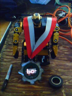
So in June I went to San Francisco to play in the RoboGames. I brought Felix, my new RoboNova and Uno, the vernerable old mini-sumo. As you can see above Felix won 2nd place in the Robo-One Demonstration contest! (Uno got his ass kicked.. he is now retired.) Matt Bauer was kind enough to make a video of Felix's performance. Thanks Matt!

Anyway, RoboGames was quite interesting. Boy howdy its a big event. I'll bet there were 200 or 300 people in the building at once at some points. Anyway, I had never seen combat robots (RC) in person. They are actually quite something to watch. They make one hell of a racket and the noise really pulls on your rubber necker strings. You feel what the spectators in Rome must have felt at the coliseum.

Nonetheless, the most fascinating contests, the ones that I still think about after the contest is over, were the autonomous navigation contests: RoboMagellan and Trinity FireFighting. The whole magnetometer thing below is all about RoboMagellan. I had never actually seen a Fire Fighting Contest. I had heard about them, but they didn't register as being very cool to me. Once I actually saw one and saw that it was really all about indoor robot localization, I became pretty interested. It would be a great opportunity to implement the 2-D-webcam-laser-range-finder concept that I saw at the SRS website and have been itching to do ever since.

The other majorly cool thing about RoboGames were the winner awards. Rather than give prizes as we have done in ChiBots, RoboGames gives electronic medals like the one you see pictured above. I LOVE MY MEDAL! I like it better than any prize I have ever won. At this month's ChiBots meeting I asked the members if they would like to drop prizes and switch over to something like the RoboGames medals. They heartily agreed! So, now we are in the process of designing an electronic medal that is specific to ChiBots. Compared to the Combots logo, our logo is pretty expensive to make so we'll just have to wait and see what it finally looks like, but I'm excited about it!

Anyway, overall I had a blast at RoboGames 2006! There is a pretty good chance I will return next year.

High Latitude Fun

So I looked some more at the data the magnetometer was giving me. For a while I thought that the X, Y and Z axis might not be aligned the way I thought they were or in the most logical way. The reason I thought that was that the Z-axis was registering some 4 times higher than X or Y. I knew it wasn't a calibration issue because I could re-orient the device that the large reading would move. I figured the large reading HAD to be due north. NOPE! The larger reading on Z was exactly what it said it was: a big magnetic field straight DOWN. WTF, I thought? Localized field? I took the device outside and there was no change.

Finally, after some looking I happened upon the USGS National geomagnetic Program website. They actually have models of the Earth's magnetic field. There is this applet that lets you select a model (they update every five years) a latitude and longitude and the current time. It then dumps out the predicted X, Y, and Z field strengths. Sure enough, the predicted value in Z was 52000 nT down and only 18ooo nT north. I had no idea the Earth's magnetic field tilted so early.

Its good to have confirmation of my readings. It was kind of a eureka moment when I ran that modeling applet. However, after that died down I realized that it kinda sucks a little in that much of the field strength is in a direction I can't use for navigation. Wait. Or is it? Hmmm. Thinking in a post is probably not good. However, just this moment it occurs to me that on the basis of the model I know which direction the Earth magnetic vector is suppose to point. That vector has a simple relationship (two rotation operations) with the "North" direction. That should fact should be usable and allow me to maintain my measurement resolution. I'm having trouble coughing up a sentence that expresses my thinking so I'll stop trying and post it later.

Tuesday, July 04, 2006

One Day I'll Be a Real hobbyist

Did some more work at long last. (Oh yeah, went to RoboGames 2006, got 2nd place in Robo-One demonstration but I'm not gonna talk about it). Anyway, I can now talk to my stupid 3-axis magnetometer over the SPI bus. The AVRLib doesn't seem to work so great. I keep dropping back to the examples in the Atmel docs, which work great. The data itself is a bit confusing, but I think that is because the axes may not be align the way I think they should be. I think the x-axis is vertical on the PCB board. Its hard to be sure by using a magnet because the field is so misshapen that it could actually be going a different direction from one sensor to the next. I'll have to figure out how to do a good job testing that.

Wednesday, February 22, 2006

RoboMagellan

So last night was a good night. My gf had a girl's night out so I got the whole evening to work on my bot. I added a 2nd story to the frame of the bot a hung the inverted joystick from it. There is plenty of clearance for it with the extra height. Boy it was harder than I expected. I only have a hand drill right now so I ended up using a 1/4 inch bit for #8 screws. Even then, I was all too often misaligned from one aluminum piece to the next. That MircoMark mill that David Cook talks about in his Intermediate Robot Building book is starting to look good. I hate to blow the $900+ or so after shipping and accessories, but I suck so bad at mechanical stuff that I need all the help I can get.

I also put a sentra bottom on the bot. Boy that stuff is hard to cut with a razor knife. Its doable, but I wish I had a better way. A band saw would probably make for a shredded edge. A water knife would probably do great work. I'll check the sofa cushions for some spare change to buy that. *snort*

Anyway, the gf has class though much of the evening so I may get some more work in. I might make some more sentra panels or I might put the wheels back on and wire up the joystick. I's like to see the data output from that thing as the bot drives.

Monday, January 02, 2006

Serial Protocol Driver

Well I've slogged my way though the skeleton logic of a serial protocol driver for the Linux CPU. I had to learn about Linux semaphores, mutexs, threads and IDEs. The IDE I ultimately chose was Anjuta as I am able to get a limited sort of prototype hint box functionality with it. Its no MSVC but the prototype hints do help once the function has been setup. (I have to put the prototypes for system calls in manually.)

Now I need to make a fake loopback protocol and test the features of the protocol driver. It should never blockup. It should enqueue several requests and return the responses in the order it received them.

It will be nice if it works. This part has been very psychologically hard for me to do because its practically difficult and conceptually simple. Those always pose serious roadblocks for me.