Friday, December 31, 2004


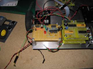
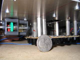
You can kind of see the problem. I find these single pad perfboards quite difficult to solder up decently. It is the interconnects that are so tedious and my technique is ugly ugly. And, as I mentioned before... it takes forever. I had another issue like this with a similar type of board, where my max 232 circuit would only work reliably at 110 baud. In contrast I have had great luck tranfering solderless breadboard circuits to schematic-to-layout editors to pro made PCBs. The two mistakes I've made with that technique are drilling holes too small and running tracing too thin for the current I expected them to carry. Both issues could be found and patched pretty easily. The issue is that the PCBs were professionally made boards and expensive. If I can get to the point where I can make my own one-off PCBs for a reasonable cost, I think I will be golden. I'll sure give it a shot next year. Hope everyone has good new year!
Posted by Hello
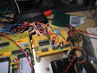
Ah, gob soldering at its finest. As you might expect the circuit does not work. The wire nest to back of the perfboard leads 5V to the PCBs on the left and runs thru 180 ohm resistors and thru those ribbon cables on their way to my IR LEDs on perf boards underneath the bot. The PCBs are known to work. I removed the MAX232 and pulled the ribbon cables off the IR LED boards leaving only the red power indication LED in series with the 270 ohm resistor, the 100K ohm Pot, and a cap or two across the 5V and GND lines of the regulator. Nevertheless there is only 44 ohms of net resistance between these lines. A 7805 out of circuit measures about 6K ohms. So, I have a mysterious partial short somewhere. Probably a whisker of a stranded wire or some such just barely making contact. When I add the load of the IR LEDs to this scenario the regulator starts to get hot, even though it maintains its 5V output. But, to add insult to injury 4 of the 16 IR LEDs are not lighting up. Could be related to the same low resistance problem, but I wouldn't be surprised if its not due to a 2nd problem with the circuit. I have yet to locate either issue. This same circuit worked like a champ on the solderless bread board. Sigh. I think I just need to abandon this form of circuit building. Its too prone to error. In the new year I am going to focus on making PCBs. I'm also going to focus on using as many SMT parts as possible. A link to an eBay item was posted on the Chibots mail list, 5000+ SMT style parts, and I snagged it for $31. With PCB making skills and SMT soldering skills I figure I should be able to make monolithic and bot specific, as opposed to general purpose modular boards, easily, inexpensively and avoid most the mind numbing details of board module interconnects. (I never seem to have the parts I need to make a decent, serviceable connection.)
Posted by Hello

Thursday, December 30, 2004


I got this little Zip Zap car as present from work. Its kinda cool. Its got a tiny little motor in it and a tiny little servo for steering. I wonder if I could make a nano sumo with this stuff?
Posted by Hello

Saturday, December 25, 2004


Woo Woo! I got a Robosapian for Xmas! He is a blast! I ran the demos and played a bit with the remote control, but really I can't wait to get him back home and take him apart! They say its a pretty hackable bot. Very exciting!
Posted by Hello
Thursday, December 23, 2004


Adventure!! I remember this game from long, long ago. Brings back memories.
Posted by Hello

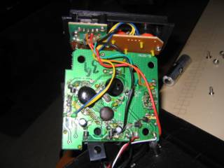
Blast! A couple of teardrop ICs and a 27Mhz crystal is all I get to see. My buddy tells me the unit was only $15 or so. So I guess that is how they keep the price down so low.
Posted by Hello

Still using the same old five button arrangment I see!
Posted by Hello

A friend of mine invited me over to his house for a couple days and there I encounterd this intersting little device that I had heard about on slashdot. Its an extra thick Atari joystick that houses enough computational power to run about 7 or 8 of the old Atari games. Games like Centipede, Adventure, Gavitar, etc. It was plain that some of the games had been re-written and had suffered a bit for that. However, on the whole the unit was a lot of fun. Naturally I wanted to take it apart to see what they used to make it go.
Posted by Hello

Sunday, December 19, 2004


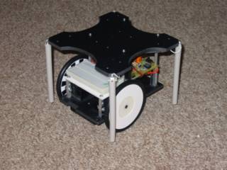
This is the same bot with the carrier board inverted. The ghost apparently left the machine in this configuration because the bot kept trying to avoid things we could not see.
Posted by Hello

Mike sent me a snap of the EM presense detection bot, the on I thought looked like a police bot. "Calling all bots! Calling all bots! A crazed robot builder is on the loose!"
Posted by Hello

Saturday, December 18, 2004

After the BDO, Tom and I went to Applebees. We discussed fighting robots of the RC and autonomous variety. After a beer or two I think we solved some of the worlds problems. I'm going to see if I can't make it to the Twin Cities with Tom for the RC bot fights there next year. "The Destruction of Tom's Robot" should make for a good blog entry. *grin*

After dinner we saw Ocean's Twelve. An entertaining film that was as much fun as Eleven.

Anyway, no more bot work for a week. I'm off to 65 degrees in Florida! Woo!

On the plus side my new $10 carry case from Home Depot did pretty well. None of my components spilled into neighboring bins or anything. I can carry just enough stuff in it insofar at components go. I still need to get one of those $30 wheeled plastic toolboxes to load robots, drills and larger items into, however.
Posted by Hello

Sigh. This is all I got done today. Really. That stupid little perfboard. The circuit is not even finished. It just a 5V regulator, the power switch, some headers and a MAX232 circuit. But it took me ALL DAY. The method of circuit construction just sucks. I am defiantely going to have to get skill at etching. That is all there is to it. Tom is going to set the BDO room up with some equipment help the etch process. I'm going to get some of that Press-N-Peel stuff and see if I can't learn to use it next time.
Posted by Hello

Tom looks on as Mike reads Tom's favorite part of the story about The Little Robot That Could, one more time. (Seriously, Mike and Tom ply the vintage logic analyzer to measure the behavior of Mike's sonic ranger).
Posted by Hello

Junk parts outside, junk food inside... as is only proper for a well put up Builder's Day Out. A new additon to BDO, the refrigerator now keeps all our favorite caffine delivery mechansims nice and cold.
Posted by Hello

Don investigates some arcane matter that requires the removal of one's right shoe. Don't ask, you wouldn't understand.
Posted by Hello

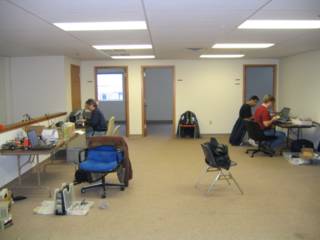
So here we are at the Builder's Day Out! In the frame we see some dedicated builders putting on their best Hunch-Of-Concentration for the camera. Mike was working on a really cool electromagnetic presence detection and navigation scheme that for some stupid reason I did not get a picture of. When he came in his robot looked like a police car with its four antennae sticking straight up, but the robot had difficulty seeing objects low to the ground. So, he inverted the antenna carrier board such that the tips were only a half an inch off the floor. The robot then began to dodge unseen obstacles in the floor. It was quite entertaining.
Posted by Hello

Ready for BDO

Well its way too early. Taking my girl to the airport, then off to the warehouse for some good robot buildin'!

Friday, December 17, 2004


Sweet! The sensors are looking good. I need a front and back caster, some wiring and my platform will be ready for software!
Posted by Hello

Thursday, December 16, 2004

Taller Standoffs Rule

Well I couldn't resist. I swapped one sensor board's standoffs with the taller ones and now its riding maybe 5 or 6 mm off the ground. Perfect!

Must go to bed now!


Here is the under side. I carefully measured the underside and placed the sensors in a ring around the middle as accurately as I could. The axles of the gearhead should be right on the centerline. With the standoff I have on there the sensors ride about an inch off the floor. I have some taller standoff that I used for the perfboard on top. I will swap them out tommorrow see how I like them.
Posted by Hello

So I have all my equipment screwed down to the aluminum chassis plate. I had to go to Home Depot and then to Radio Shack and then to Ace Hardware to find enough of the right kind of screws and nuts to complete the thing. I lost the screw I had tape to a piece of paper before I got to Home Depot. So then I went to Radio Shack to buy some of their little standoff that I know match the others that I have. Then I went back to Home Depot, but they didn't have the screw. I found them finally at Ace Hardware. They seem to have a pretty big screw selection. I should probably move the battery packs back. I can only get one screw into them because of the motor and the bot is way heavy in the front.
Posted by Hello

Drilling

I drilled pretty much every hole in my aluminum chassis plate last night and started screwing down circuit boards. In honor of the the occasion I named my maze robot "Standoff City" because he is going to use up every standoff I own. I need to find cheaper way to make circuit modules. I am thinking that the three-hole pattern perfboards might be the way to go. With the three hole pattern it seems like you could T-Tap connections without gobing the solder together. I just want an easy-to-construct mechanism that builds permanent, low-profile (e.g. not wire-wrap (bletch)) circuits for not a lot of money. Chemical etching is kinda nasty and you have to drill for components I usually use. I am not all that swift at drilling. If I could master SMT soldering then maybe all I would have to drill are the vias. Tom G. offered to keep etching equipment at the BDO room. So maybe that is the way to go. I'll still at least try the three-hole thing though, as it suits my incremental circuit building leanings.

Tuesday, December 14, 2004


Here is a rear photo of the MarkIII chassis that shows what I had to do to get the servos mounted. Since I didn't buy the Mark III control board I first had to make an aluminum plate to retain the top portion of the mounting posts. Then I had to go to HomeDepot to find some longer screws and washers as the ones that come with the Mark III were not long enough to account for the fact that the high-torque servos cannot be mounted with their flanges flush to the mounting posts. I also needed spiral scroll saw blades to cut the aluminum plate. The guy at Home Depot who helped me find all this stuff was an out of work software engineer whose job had moved to India. I felt really bad because I have been helping facilitate my company's use of Indian contract programmers for a few months now. But, I need a job too.
Posted by Hello

This is the current state of my new mini-sumo bot. Uno, poor thing, had quite a bad time of it at the November contests. He was shorting out and rebooting when I pressed the start-of-match button. Bad, bad, bad. So Uno is retired though I may rework him in an attempt to rejuvienate him. Nonetheless, work has begun on Matador! I bought pieces of the Mark III mini-sumo kit to get me up and going pretty quickly becuase I wanted to spend most of my time on the maze bot. However, I bought the extra high torque servos that the jujun.org store offers. The store says I'll be 4mm too wide with these servos but I've partially drilled out the wheels and I think I've gotten that space back. I'm within half a mm of the 100mm limit in anycase. I need to get the offical bounding box from the club and see if I can cram him in. As you can see I have an OOPIC II atop the bot. Eddie Wright dontated it. (That Eddie is a nice guy, eh?) Anyway, I'll see if I can't whip up an algorithm a bit more complex than Uno's spin, detect, charge algorithm. Finally, I'm using the standard line detectors and have yet to make a decision on the opponent sensors.
Posted by Hello

This is the underside of my maze robot. You can see I'm using those crazy Tamiya gearbox and motor assemblies. They work OK really. Tom G. gave me a couple of swank gearhead motors to use for this bot but they turned out to be a touch too wide with those line sensors set in the middle as they are. I have to be no more than 11" wide. Anyway, the center circuits are my line sensor arrays. Each black box is a PCB mount package with one IR LED and one IR phototransistor. I soldered wire-wrap wire to bring each sensor package upto the 14-pin headers. Soldering to the headers was hard. The boards took a long time to make. I really need to get a better technique. I really need to take another stab at not screwing up board etching. :)
Posted by Hello

This is the current state of my attempt at a solution to the maze. Here you see an 8"x8" Aluminum plate with wheels. Across the top I've placed equipment to try to get an idea of how my space allocation is doing. The left middle board is Eddie Wright's ATMega32 DevBoard. Above and below that are my line sensor comparetor boards. (They translate signals from the IR phototransistors into a hard 0v or 5v signals for the microprocessor, though Eddie tells me I probably could use the signals directly) The right middle board is my H-Bridge circuit that I had made up using ExpressPCB. The chip is 4 1A half H-Bridges. Also note that I've pasted encoder stripes on my wheels, though I don't yet have a circuit to measure them.
Posted by Hello

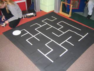
So this is the challenge. The bot must solve this maze, autonomously, in the lowest time out of three tries. At the November contest the best was 23 secs.
Posted by Hello

First Post (w00t)

Ok. My first blogger post. Now lets see if I can figure out how to use this hello thing and whether or not I will be able to use the mechansim as a free photo log for my robot building and other misc apsects of my life.